For a few weeks now I’ve been researching all that I’m going to need for my solar system and electrical setup and I feel pretty confident about the majority of it but I still have one question lingering in the back of my mind that I’ve yet to answer:
If I’m going to have my 120Ah 12V DC battery ran to an inverter to power my AC devices (laptop charger, camera batter charger, etc.), how can I go about also running it directly to my DC devices (roof fan, LED lights, fridge)?
I know this may be a rookie question but I’ve never done anything major with electricity before and I want to make sure that it’s done right the first time. I’ve searched for advice regarding this specifically and haven’t been able to find anything just yet, which may just mean that I’m over thinking this, but I would appreciate any input whatsoever!
Run a battery cable sized wire to a 12v fuse box, and at the fuse box, Y it off to the inverter. I would also add an appropriately sized fuse or circuit breaker between the battery & the fuse box, and between the fuse box and the inverter.
I would also suggest an isolator to keep your house battery charged.
Cheers!
"Be creative & recycle, reuse, & repurpose." ~ The Camper Van Man
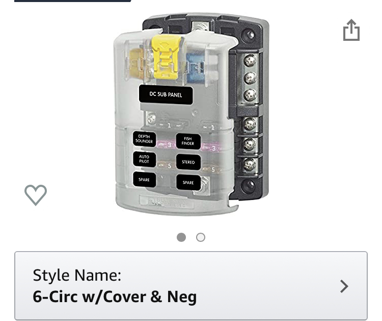
I’ll only have just three DC appliances (roof fan, lights, fridge) so I think this is the amount of circuits I’ll need.
My devices amperage are as follows:
Lights: .75 Amps
Fan: 2 Amps
Fridge: 3.75 Amps
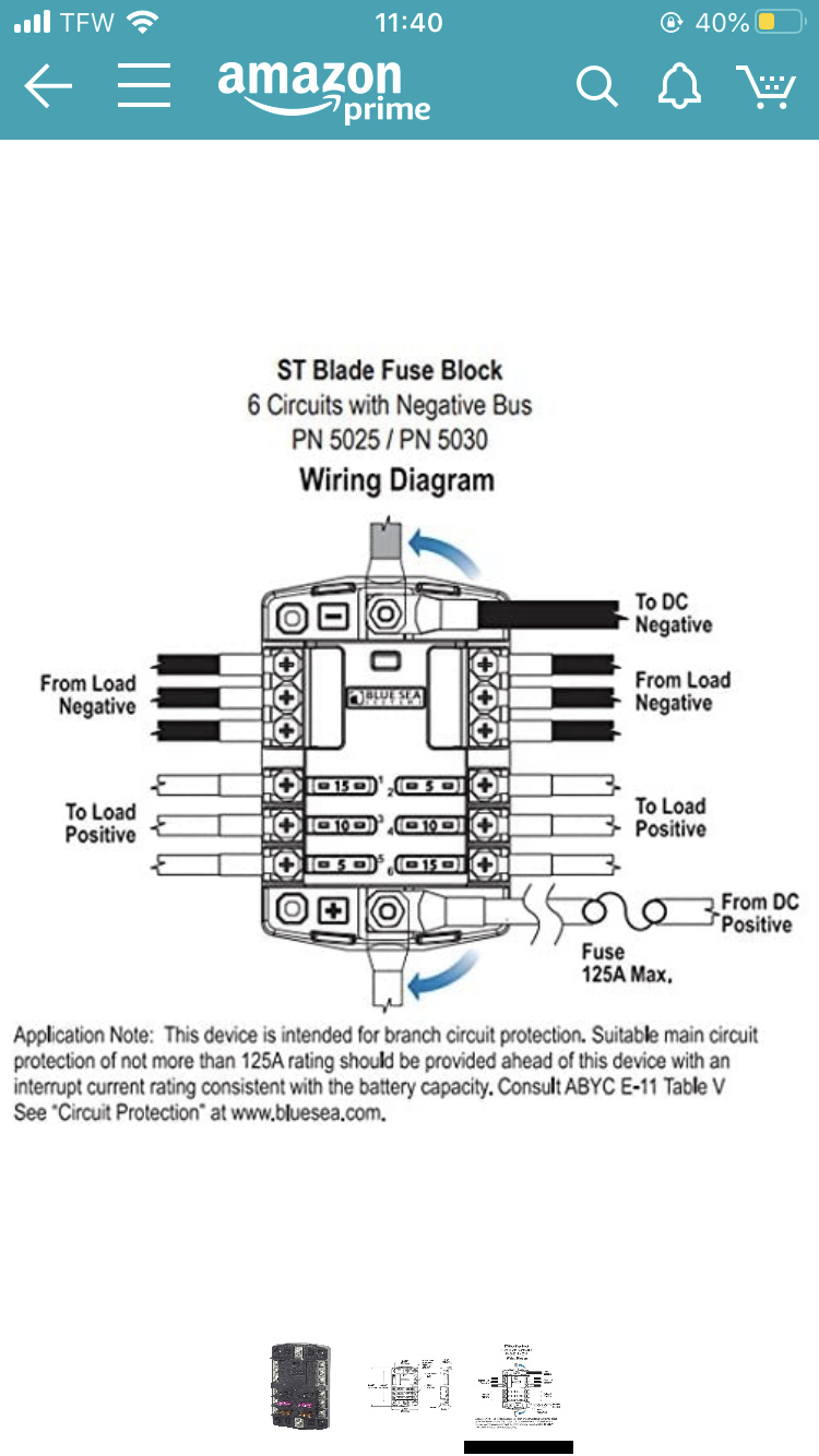
The positive battery cable connects to the large screw on the bottom, the positive cables of each DC appliance connect to one of the six screws on the bottom, and then their negative cables connect to one of the six screws on top, which are the negative bus bar (I think), and the power then flows back to the battery through a negative cable which is attached to the large screw at the top. Is this correct?
Sorry for so many questions, I’m just trying to figure out as much as possible before starting this essential part of my build!
Everything on your list I run off of DC, the only time I plug the inverter in if I want to run the vacuum.
That said the inverter is wired to the same house batteries.
At the bottom of your fuse box diagram, there appears to be a large stud at the bottom center for power going into the fuse box, and it says to put a fuse in that line of a max of 125 amps. So your cable should be sized to carry 130+ amps @ 12 vdc and it should connect to the stud with a ring terminal.
The Y is an equal sized cable, also with a ring terminal on the end and equal fuse. It attaches to the same stud at the fuse box.
So if the positive cable going to my inverter is a 130 amp cable that connects to the stud at the bottom of the fusebox, should the negative cable going to my inverter also connect to the fusebox at the stud on top?
If your house battery is grounded to the chassis, then the inverter can be grounded to the chassis as well to save a longer cable run. If not, then yes connect it to the negative on the fuse box. The negative cable should be the same size as the positive cable.
Some inverters draw power even when they’re turned off, so I would add a battery cutoff in the positive line between the fuse box and the inverter to prevent this. This is in addition to a fuse, but a circuit breaker could provide both functions.
Cheers!
"For every complicated problem there is usually a cheap, easy, simple, & safe solution." ~ Road Warrior
My inverter is only rated at continuous 700 and peak 1400 watts, am I wrong to think that a cable rated at 130 amps and a fuse of 125 amps would allow too much current into the inverter and fry it?
And does the fuse going to my DC Fusebox need to be rated so highly as well? I plan on pulling far less than 125 amps with all of my DC devices combined
My inverter is only rated at continuous 700 and peak 1400 watts, am I wrong to think that a cable rated at 130 amps and a fuse of 125 amps would allow too much current into the inverter and fry it?
I’m actually worried in the opposite direction. 1400 watts peak + 20-25% inverter overhead could try drawing as much as 145 amps, which would blow a 125 amp fuse/breaker.
Cheers!
"For every complicated problem there is usually a cheap, easy, simple, & safe solution." ~ Road Warrior
And does the fuse going to my DC Fusebox need to be rated so highly as well? I plan on pulling far less than 125 amps with all of my DC devices combined.
With an inverter that size, even 125 amps might not be enough. What are you planning on running on the inverter?
Cheers!
"For every complicated problem there is usually a cheap, easy, simple, & safe solution." ~ Road Warrior
Oh crap I was only calculating with the continuous wattage, thank you for correcting me!
Okay so it sounds like I should size down my inverter, I plan on only running small things like a laptop charger which draws around 3 amps to charge with.
If I were to use an inverter with a peak of 1000 watts, its overhead of 125% would create a max draw of ~105 amps.
So I would still be able to use a 130 amp cable (let’s say 1 AWG) to the fusebox with a 125 amp fuse and a 130 amp cable with a 125 amp circuit breaker going to the inverter, correct?
Can you get a car charger for your laptop? They are much more efficient, and you could eliminate the inverter all together.
If you must use an inverter, and it’s past the specs of the fuse box, it can be attached directly to the battery, or to the isolator, with a fuse/switch or circuit breaker before the inverter.
Find the specs for your alternator, then add 10-25% for the isolator size. You always want the cables & equipment to be over rated for the maximum possible going through them. This helps eliminate problems down the line.
Cheers!
"For every complicated problem there is usually a cheap, easy, simple, & safe solution." ~ Road Warrior
Dude thank you so much for giving me all of these answers, you’re a godsend! I just have one more question:
I have no alternator in the equation because my battery is being powered off of a 200 W solar panel system and not my vehicle, what should I use instead to determine the size of the isolator?
An isolator is used between your starting battery and your house battery to charge your house battery while driving. This charge is coming from your vehicle’s alternator, so we size those wires in accordance with how many amps your alternator is capable of putting out, plus 10%+ extra for good measure.
Cheers!
"For every complicated problem there is usually a cheap, easy, simple, & safe solution." ~ Road Warrior
So if I still plan on connecting an inverter to the battery, what type of switch would I install on the positive going to it in order to separate it from my battery and keep it from draining?
Also remember if you add in an isolator, that since your alternator is grounded to the vehicle your house battery will also need to be. You should also you take into consideration the entire length of your circuit when picking a wire size for it. The entire circuit length is to the device and back. Larger gauge wires are eventually needed for longer circuits. It may not be an issue in a van but it should definitely be taken into consideration.