Hi everyone,
First, thanks for your interest and time spend in my topic.
To introduce myself: my electrical knowledge could be resume to god google told me this.
As we all know, internet is a big pot with nice stuff and awful lies, so I am posting here a diagram that we made, we hope that you will have advices, opinions and comments that will allow us to improve seriously our project. Please, be patient, we are learning ![]()
If you have the time, read about our story, if not, jump this quote section ![]()
A bit about the history of caterpillar, our van.
Caterpillar is a T5 - hitop - 2012 - 150k. It has been bought by my gf -J- in 2017.
After buying the van, J and her brother started building the van, making a kitchen side, a bed, and installing
- 2x100w flexible solar panels made in china + PWM + AGM 150hA + inverter 1000w. And of course some addons - gas cooker for the kitchen, husky fridge etc-
After I arrived in J and caterpillar`s life, the 3 of us started to travel around europe. We made nice trips but systematically we were out of power on a daily basis.
Therefore, we know that our supply of electricity is bad, and that our storage of electricity is also bad. We also had several issues with the flexible solar panels - they burnt.2023 is the year of the change, and we got both fired from our work, witch clearly is a sign from the divinity of the vans, telling us to restart our caterpillar project, but this time to make it slightly more seriously.
If you dont have the time, move quickly to here ![]()
So we restarted our research in the google bible and we found a bit of what we want and also a bit about what we can afford, in terms of time but also in terms of money.
On the short term : buy again 2x100w solar panels rigid, couple them in serie with a MPPT, build on a quick way a safe electrical supply, even if we know that we will be in short. Why quick? Because it is almost summer, so it is easier for us to get each day our battery full.
On the mid term, increase our system with:
- 2x100 solar flexible, wich will rise our harvest capacities to 4x100w.
- Add a 2nd victron MPPT -the panels being 2x flexible + x2 rigid they will have different specs-
- Add a 2nd battery AGM
- Create a B2B and shore line
- Add a roof window
Our current consumption is I would say low:
12V:
- 1x water pump,
- 2x USB lines, computer,
- 3x strip of leds
220V
- fridge, computer and drone charging.
*Fridge has 2 modes, the compressor ones needs 220v, the maintaining of the temperature can go on 12v.
Usually we connect it on 220v but don’t keep it on all the time.
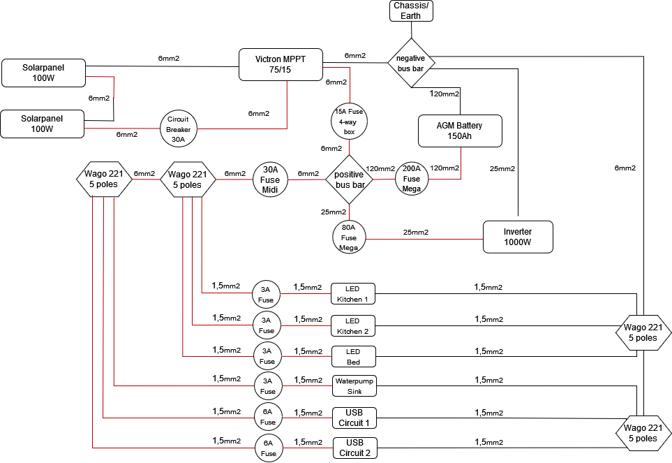
![]() So here is our electrical diagram link:
So here is our electrical diagram link:![]()
One important thing is that we plan to make all the connections with ring or blade connectors.
Except if you advice us to make it otherwise ![]()
Also, in the diagram it shows that for the 2xMEGA and 2xMIDI fuses they are mono holders.
We are planning to try to get 1 Holder for all the MEGA fuses and 1 holder for all the MIDI fuses.
Again, except if you advice us to make it otherwise ![]()
A few questions :
-
From the negative bus bar should I link a wire to the chasis of the véhicule ? If yes, what should be the thickness of the wire ?
-
In general terms, are there too much / not enough/ not well calculated fuses/breaker/protections?
-
Do we need a 25mm wire from : A- 150amp to the battery ? B- from battery to bus bar ? C- from positive bus bar to 80amp fuse, inverter and back to negative bus bar ?
-
Is it ok to have 6mm wire that splits into several 1.5mm wire through the wagos on the positive current - fuse box - negative current ? The wagos choosen are the 221 ones.
To finish, for our dear friends non metrics I added the conversion to AWG, the cables proposed by this diagram are:
1.5mm ![]() 16 AWG
16 AWG
6mm ![]() 10 AWG
10 AWG
25mm ![]() 4 AWG
4 AWG
Now it is YOUR turn
![]()
And please, dont hesitate to make each single comment that you find useful, we are here to learn and to try to build the best van that we can !
Thank you for your time and patience reading us !