Hello! I am Bethany and I am in the process of building out a Ram promaster and I finally got around to doing a rough draft of my electrical diagram. It took an embarrassingly long time to make (not great with computers! ) so please be kind to me and let me know if you have any suggestions or questions! Love -Bethany!
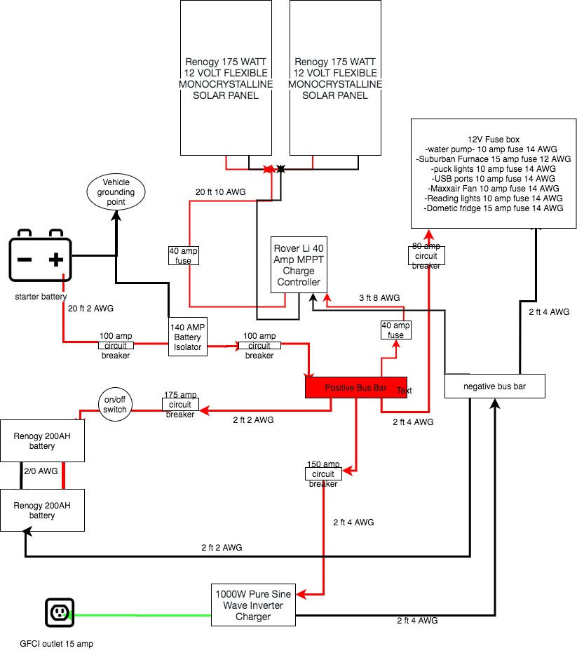
You have 80 amps worth of appliances running off of the fuse panel. Are you planning a way to automatically shut it off if the batteries are drawn too low? It would be an expensive mistake to over-draw the batteries. A simple way to do that would be to upgrade the charge controller to an 80 amp model and run the fuse box from the load terminals on the charge controller only. Be sure the controller has the battery protection feature.
There should also be an independent ground strap between the chassis/metal enclosure of the inverter and the body/frame of the van. Same with the negative terminals of the batteries.
Good quality inverters will shut themselves off if the voltage goes too low, so can be connected as you drew it (but add a ground strap).
@Axel - Probably half the amps. Those are fuse ratings. I’ve never worried about a cut off. I see the voltage all the time though.
I imagine those batteries are AGM due to them being 200ah and I think that’s all renogy offers in that size. With the solar having just installed that myself, I might pick a different battery type.
We had to set ours to user defined settings when setting up our charge controller. Something about equalization that I do not quite understand yet and being bad for certain agm batteries. We have not found a way to set max voltage specifically for a battery though. 12.8 I believe for agm. 12.7 for everything else. So I wonder if the panels are actually topping the battery off or not. I am going to upgrade to lithium at this point. The solar is great though. We were pushing ~15 amps yesterday and still pushing ~5 amps in a light rain. That was with 3 100 watt panels. My friend has 4 and pushes ~20amps. Starting to average it out at 5amps per 100 watts in my head.
1 Like
Yes they are AGM batteries. I initially had lithium but since I am using a small inverter (I don’t plan to use DC power much for anything) the lithium battery was not compatible. And upon further research I like AGM batteries better since lithium batteries are easily damaged if charged in freezing temperatures. I live in a state that gets quite cold! but it’s also a very sunny state so I’ve never had a problem in a previous build with the same amount of watts in my solar set up and a smaller battery bank. My batteries never came close to low.
If they’re AGM, then they should be charged at about 14.5 volts, then when charged the controller should “float charge” them at around 13.7 or so. with no charge going in (nighttime), AGM batteries should produce about 12.8 volts. But all this changes depending on temperature. Your controller should have a temperature sensor that decreases the charging voltage when it gets hot.
Make sure the charger does not go into any kind of de-sulfation mode with AGM batteries, as that will damage the batteries. De-sulfation is only good for flooded cell batteries that can be topped off with distilled water; AGM batteries will vent if subjected to that, and can’t be topped off - the battery will eventually fail.
I don’t see the return (negative) bus bar strapped to the chassis. That is probably a simple oversight in the drawing. If not, i.e. you were relying upon the MPPT controller to make the connection, well, don’t. The ground strap doesn’t have to be super heavy. It is primarily a return for the starter battery loop.
In my wiring, I didn’t put a switch between the bus and the inverter. My build is all electric, so I have a large inverter and very heavy current draw.
I put either a switch or a breaker between each power source (house bat, starter bat, and solar) and the bus, and one more between the bus and the 12v distribution. These were mostly for convenience (i.e. isolate stuff when working on the wiring).
One thing that gave me fits: Using a cheap thermal breaker caused no end of problems in the main battery loop: they would either trip way too soon, or, worse, not trip, but momentarily disrupt the circuit and cause the inverter to shut down, lights to flicker and who knows what to a refrigerator compressor (I am still waiting for my refer).
After four rewires and several breakers I finally switch to a 250A fuse and a 275A switch. A tad more loss across the switch and fuse, but now totally reliable. (NB, the inverter was renogy and had a remote on/off switch)
Thank you for the input! But this build has been finished for over a month and everything is working nicely 