Hello,
First post and first conversion for this rookie. Never worked with electricity before. Looking for help proofreading and editing my custom solar wiring diagram.
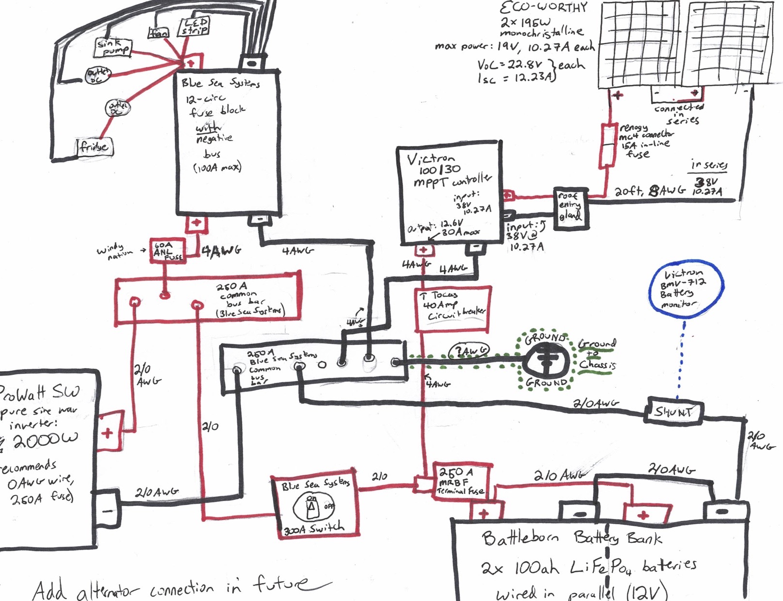
Open to critiques and suggestions of wire sizes, components, connections, etc
I don’t understand grounding. Can I ground just once from the negative bus bar as shown? What size wire do I need to ground from the bus? Is it even necessary?
And is it easy to add an alternator connection after my build?
You only need to ground to the body if something calls for it, or you attach an isolator as the alternator is grounded to the battery. It is also dependent on how you wire your circuits. In DC you can just run a positive and then use the body as the negative only needing to run a single wire. I’m not a fan of this or sure if it is even a thing companies do anymore. It is preferable to run both wires, positive and negative.
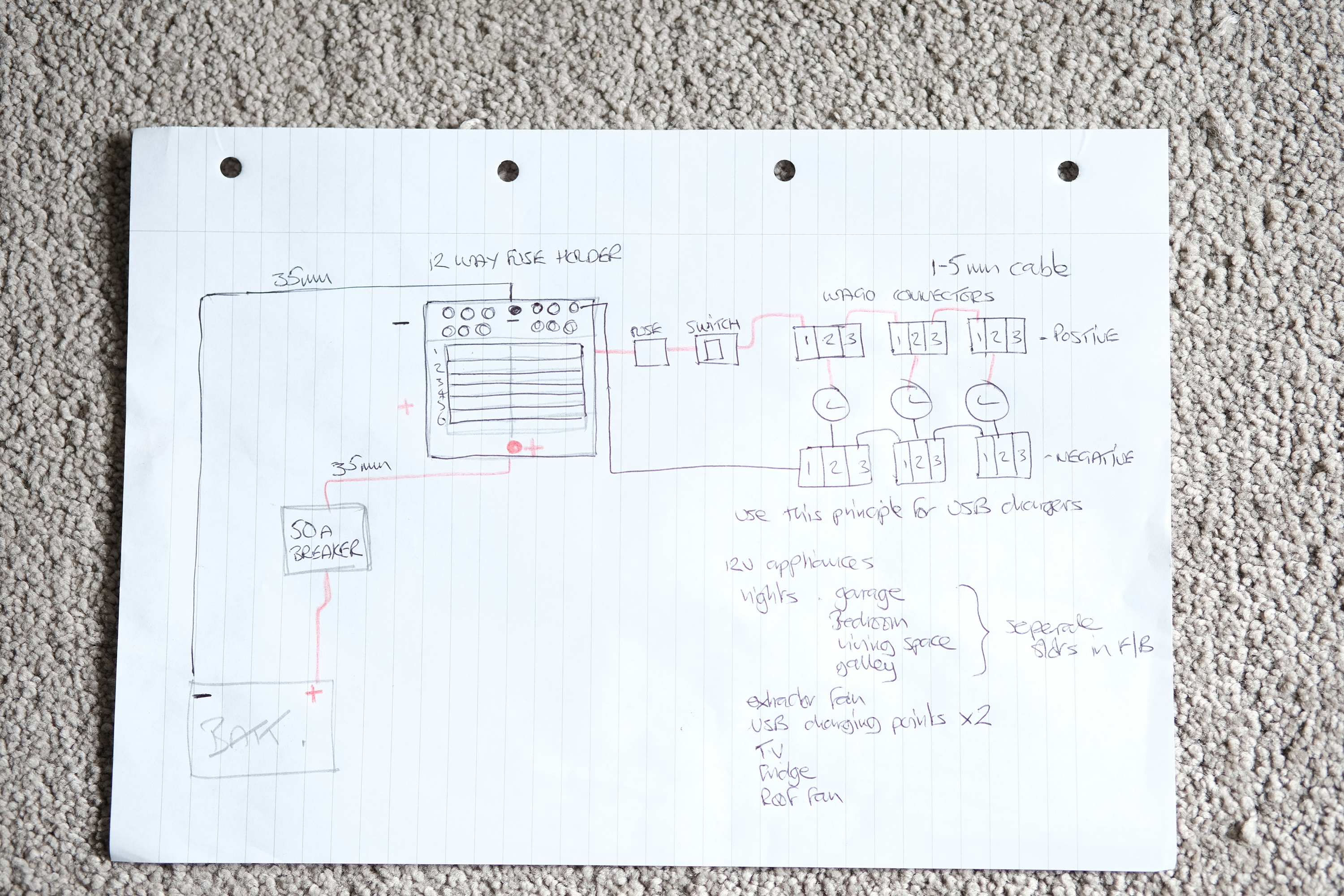
This was primarily a test for my light but the same can be applied to any USB charging points
the “Wago” connectors are brilliant they are very good at err . . . connecting you can get them in 2 -3 -5 way configurations
take a look at this guys diagrams it all looks very complicated but in fact its very simple this is what I shall end up with everntually
12v for the van day to day running
solar briefcase from Renogy to top up the batteries and a decent
Generator as a back up to handle all the AC requirements when not plugged into “shore power”